Oufu Optical Fiber Cable Co, Ltd
Aderesi: Shenyang, Liaoning, Ubushinwa
Umuntu uhuza: Umuyobozi Zhang
Terefone: 400-964-1314
Terefone igendanwa: 86 13904053308
کیاWhatsapp & & Wechat
2025-09-29 1103
 Www.adsscable.cn
Many people think construction is just about "laying cable," but there's a lot Byinshi to it. From preliminary preparation to final testing, negligence at any stage can create hidden problems. Today, we'll break down the five key steps to ensure quality in communication optical cable construction, helping you achieve a right-first-time, safe, and reliable optical cable deployment.
Detailed Planning and Preparation Before Construction
Preparation is the cornerstone of success. Before work begins, detailed site surveys and route re-measurement must be completed. You need to confirm the specific path and length for the optical cable installation and check if facilities like conduits, ducts, or poles meet the installation requirements.
Material inspection is also crucial. Once the optical cable arrives on site, it should be tested upon opening the reel. Check the specifications, model, and reel length, and use an OTDR to inspect the fiber attenuation constant, ensuring the optical cable wasn't damaged during transport. For instance, in a 2023 campus network project, our team identified a crushed cable during this initial test, preventing major rework later.
Universal Core Specifications for Cable Installation
Regardless of the installation method, some universal specifications must be followed. First is the bend radius. During construction, the optical cable's bend radius should not be less than 20 times its outer diameter. This is especially important when pulling through conduits and around corners.
Second is tensile force. Never pull directly on the fiber cores of the optical cable. The tension should be applied to the strength members, and the speed should be constant, typically not exceeding 10 meters per minute. Counter-intuitively, faster pulling speeds can increase friction between the cable and the conduit wall, raising the risk of damage.
Detailed Installation Methods for Different Scenarios
Communication optical cables can be installed in various ways, chosen based on the environment.
Duct Cable Installation: This is one of the most common methods. Before installation, sub-ducts should be placed inside the main conduits, and the cable is pulled through these sub-ducts. Inside manholes, the optical cable needs protection, like flexible conduit, and should be secured on racks.
Direct Burial Cable Installation: The key here is burial depth. The trench should be at least 0.8 meters deep in ordinary soil, and at least 1.0 meters under roadways. When backfilling, start with 30cm of fine soil or sand, then backfill with the original soil, and lay a warning tape above.
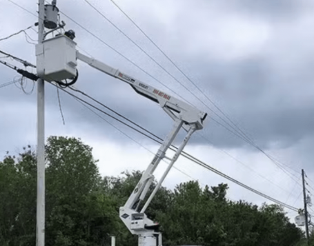
Aerial Cable Installation: Ensure poles are secure and firm. The cable height when crossing roads should be no less than 7 meters. When crossing over power lines, a protective sleeve must be used for insulation.
The Precision Process of Splicing and Termination
Splicing is the most technically demanding part of communication optical cable construction. It should be performed by specially trained personnel using the fusion splicing method, aiming to keep the splice loss for single-mode fiber below 0.05dB.
The splice point must be protected with a heat-shrink sleeve and neatly coiled into the splice tray inside the closure. The splice closure itself must be sealed against water and installed securely. According to data from the FTTH Council, over 35% of optical cable failures occur at splice points, making the quality of work here critical for long-term reliability.
End-to-End Testing and As-Built Documentation
Testing after construction is the final checkpoint to verify the results of the communication optical cable construction. An OTDR must be used to test the total attenuation of the fiber link and observe the backscatter signal curve to ensure there are no defects.
After passing the tests, complete as-built documentation should be compiled and submitted. This includes, but is not limited to: the optical cable layout diagram, splice point locations, fiber color sequence table, and all test records. Comprehensive documentation is the "map" for future network maintenance, expansion, and troubleshooting – its importance cannot be overstated.
Comparison of Core Requirements for Different Installation Methods
| Characteristic | Duct Installation | Direct Burial Installation | Aerial Installation |
|---|---|---|---|
| Main Advantage | Good mechanical protection, easier expansion | Route is hidden, relatively high security | Short construction cycle, lower initial cost |
| Key Control Point | Sub-duct placement, fixing in manholes | Burial depth, backfill protection | Installation height, wind resistance |
| Common Challenge | Congested ducts, high friction | Affected by soil type and existing utilities | Susceptible to weather and external environment |
Five-Step Operation Guide for Achieving Low-Loss Splices
Sheath Removal and Cleaning: Use dedicated tools to strip the cable sheath, precisely removing the outer jacket and strength members. Thoroughly clean the fiber of any filling compound using alcohol wipes.
Fiber Preparation: Use a fiber stripper to remove the coating. Then, use a cleaver to create a fiber end-face that is flat and free of defects.
Placement and Fusion: Carefully place the two prepared fibers into the fusion splicer's V-grooves, ensuring they are aligned and not touching the bottom of the groove.
Fusion and Evaluation: Start the fusion splicer's automatic program. After splicing, the device will display the estimated loss. Visually inspect the splice point to ensure it is uniform and smooth.
Heat-Shrink Protection: Move the heat-shrink sleeve to center it over the splice point and place it in the heating oven to shrink. After cooling, coil the fiber neatly into the splice tray.
⚠ Warning: Common Construction Misconceptions
Never neglect leaving service loops to save effort! At splice points, equipment access points, and obstacle crossings, sufficient cable length must be reserved as per specifications (typically 8-10 meters on each side of a splice). Insufficient slack creates immense difficulties for future splicing and maintenance and could even render the entire cable section useless.
Communication Optical Cable Construction Quality Checklist
[ ] Site route re-measurement and technical briefing completed.
[ ] Optical cable tested upon reel opening, confirmed performance is good.
[ ] Bend radius and tensile force during installation consistently met specifications.
[ ] All splice loss tests meet standards, splice closures are sealed properly.
[ ] End-to-end OTDR attenuation test passed, all as-built drawings and documentation are complete.
Frequently Asked Questions (FAQ)
Q1: Is the minimum bend radius requirement the same during construction and during maintenance?
A: No. The requirement is strictest during construction, at 20 times the cable diameter. After installation, the static bend radius for long-term use can be reduced to 15 times, but sharp bends are still strictly prohibited.
Q2: What should I do if the conduit is blocked and the cable cannot be pulled through?
A: First, try using a conduit rodder or air blowing to clear the blockage. If that fails, consider changing the route, or use micro-duct and micro-cable blowing techniques. Never force the pull, as it can damage the cable.Www.adsscable.cn
Q3: What is the safe distance for direct buried optical cables from other underground utilities?
A: Standards require a minimum parallel separation of 0.5 meters from power cables. For crossings, the vertical separation should be at least 0.25 meters, with insulating protection applied for a certain distance before and after the crossing point.
Q4: What are "ghosts" in an OTDR trace, and how can they be eliminated?
A: "Ghosts" are caused by multiple reflections after a strong reflective event (like a connector). They can be eliminated by adding attenuation, for example by coiling a short section of "pseudo-fiber" at the front end of the fiber under test.
Q5: Can optical cable splicing work be done in rainy conditions?
A: It should ideally be avoided. Moisture and impurities in the air can be trapped inside the closure during splicing, affecting long-term reliability. If it's absolutely necessary, use a weather shelter or splicing van to ensure a dry and clean working environment.